

Holster Fitment Notice
While we’ve designed the Carbon Mitigation Device (CMD) to maintain compatibility with most duty and tactical holsters, we cannot guarantee fitment across all brands or models.
All holsters are manufactured differently, and there can be slight variations in plastic thickness, molding, and internal ribbing that affect the way the light and CMD seat inside.
We’ve confirmed that the Alien Gear Rapid Force LVL3 and Safariland 6000 series holsters fit the CMD-equipped lights right out of the box, though some users may find that minor adjustments — such as adding shims, spacers, or lightly trimming internal ribbing near the light head — may be required for a perfect fit.
Every holster setup is unique, and we appreciate your understanding as we continue to refine compatibility across different platforms.
Disclaimer
Dark Matter Concepts is not responsible for any damage that may occur during the removal of the TLR-1 bezel. The TLR-1 bezel is installed by the manufacturer using factory thread-locking compound and requires proper tools and care for removal. Customers assume full responsibility for the removal process, including any damage to the light or any voiding of the manufacturer’s warranty that may result from disassembly.
STreamlight TLR-1 Bezel removal
STL1V1 TLR-1 CMD Installation
STL1V1 TLR-1 HLX CMD Installation
SVX3V2 x300 CMD Installation
SX3V1 X300 CMD Installation
Prepping your light for the CMD:
In the most ideal state, the CMD would be attached to a brand-new weapon light with no carbon build up on the outside of the light bezel. If the CMD is attached to a used light with carbon accumulation on the outer diameter of the bezel, proceed to remove as much carbon as possible safely.
*Note: Light bezels with significant carbon build up may impact tolerances and the ability for the CMD clamping mechanism to be retained to the light bezel. We do not encourage this.
Equipment needed:
Allen wrench (0.050” size – included)
Q-tips
Clean rag
Isopropyl Alcohol
Installation instructions:
1. Unscrew the locking screws out of the CMD.
a. Clean the screw threads using a Q-tip dipped in isopropyl alcohol to remove any particles or oil.
Clean the CMD’s internal threads the same way.
2. Clean the internal diameter of the CMD using isopropyl alcohol and a clean rag.
3. Install the CMD on the light head.
4. Apply Vibra-Tite to the screw threads and re-install the locking screws. (Do not tighten them yet.)
5. Install the CMD on the light head. The screws should be loose enough to where the CMD can slide on the light head without resistance.
6. Position the CMD as shown in Figure 1. Ensure it is centered on the light and that the “legs” are resting against the X300 as shown.
7. Hand-tighten the screws so they are snug but not overly tight.
a. Note: If the Allen key begins to deform, you are over-torquing the screws.

Figure 1: “Legs” (circled) are resting on the light body. CMD is centered.
Making your holster compatible with the X300 SX3V1 CMD
Note: Due to dimensional variances in holsters, some may require minor adjustments for the CMD to fit properly. These adjustments do not weaken the overall structural integrity of the holster if the directions are followed.
Be sure to try and holster the pistol with the installed CMD first to determine if any adjustments are necessary as many holsters may not need adjustments.
SSR1/MOPR1 Rifle CMD Installation
Prepping your light for the CMD:
In the most ideal state, the CMD would be attached to a brand-new weapon light with no carbon build up on the outside of the light bezel. If the CMD is attached to a used light with carbon accumulation on the outer diameter of the bezel, proceed to remove as much carbon as possible safely.
*Note: Light bezels with significant carbon build up may impact tolerances and the ability for the CMD clamping mechanism to be retained to the light bezel. We do not encourage this.
The “middle-back” of the CMD should be directly towards the muzzle blast.
Equipment needed:
Allen wrench size = H2.5, aka 2.5mm
Digital in/lbs. capable torque-screwdriver or equivalent
Q-tips
Clean rag
Installation instructions:
1. Unscrew the locking screw out of the CMD.
a. Clean the screws threads to remove any particles and oil.
b. Clean the CMDs’ internal threads to remove any particles and oil.
c. Using a very slight amount of Vibra-Tite, apply to the screw threads and re-install the locking screw. (Do not tighten CMD clamping arms yet)
2. Clean the inside diameter of the CMD.
3. Install the CMD on the light head. The screw should be loose enough to where the CMD can slide on the light head without resistance.
4. Position the backside of the CMD where the muzzle blast is coming from.


We recommend that the distance between the top of the clamp and the bezel face be greater than or equal to 0.2”.
b. Once ideal position is found, slightly tighten the locking screw to retain the CMD in the needed position.
c. Using your in/lbs capable torque wrench, tighten the locking screw to 8 in/lbs.
Safariland 6000 Series
Each SX3V1 CMD will come with holster specific washers. These washers are used to widen the end of the holster by approximately 1-2mm to allow for seamless and reliable holstering (if needed). Safariland washers can be seen in Figure 1.

Figure 1: Safariland washer
Remove the holster plug (this will remain removed).
Unscrew the cross-locking screw as seen in Figure 2.
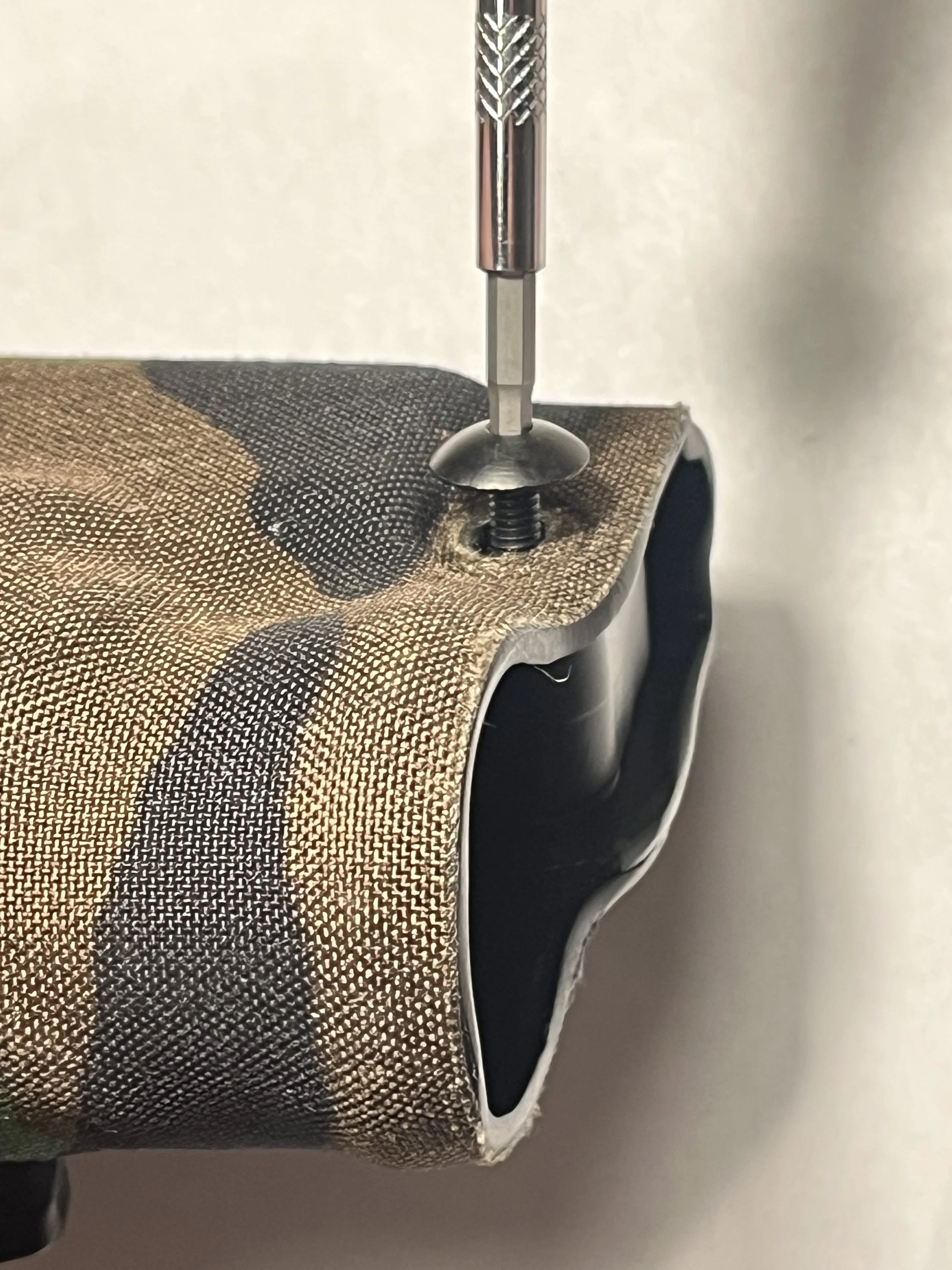
Figure 1: Safariland washer
Figure 2: Removing cross-screw
3. Install ultra-thin shims in-between the barrel indexing nub and the holster on both sides, ensuring that the washers are centered around the screw hole cut out. See Figure 3.

Figure 3: Shims installed
4. Applying Vibra-Tite to the cross-screw, reinstall the cross screw and tighten to a snug condition. Avoid over-tightening.
Alien Gear Rapid Force LVL3 (older variant)
Older LVL3 Rapid Force holsters have no internal ribbing as seen below in Figure 1.
Alien Gear Rapid Force LVL 3 (older variant) shims are shown in Figure 2.

Figure 1: Older AG LVL 3 Rapid Force with no internal ribbing

Figure 2: Shims for older AG LVL3 holster
1. Unscrew the screws highlighted in PINK below in Figure 3.
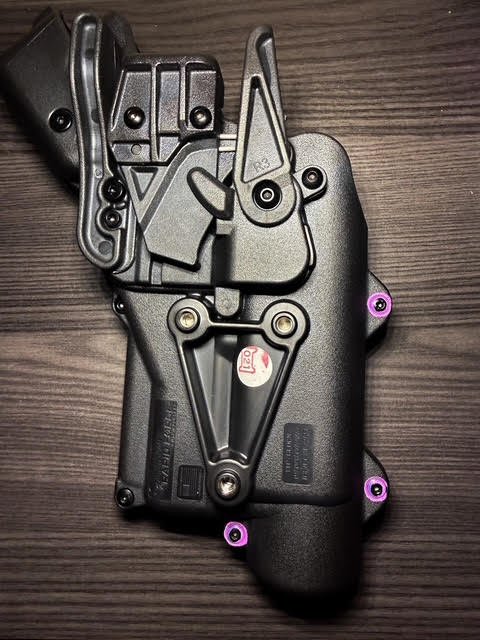
Figure 3
2. Install shims indicated in Figure 3, ensuring the shims are flush with the slide of the holster and do not protrude. See Figure 4.

Figure 4: Shim installed
3. Reinstall all three screws and tighten them to a snug fit. Avoid over tightening.
Alien Gear Rapid Force LVL3 (newer variant)
The newer variant of the Alien Gear Rapid Force LVL3 has internal ribbing that interferes with the CMD and must be removed.
Ribbing is shown in Figure 1. Removing these ribs should not compromise the structural integrity of your holster if done properly.

Figure 1: Remove all ribbing around the internal circumference where the light head sits in the holster, stopping at the blue line.
1. The area of internal ribbing to be removed is called out in Figure 1, stopping at the blue line.
2. Using a Dremel with a cylindrical sandpaper attachment, carefully remove ribbing. See Figure 2. Important: Take care to only remove the ribbing—do not cut into the holster body.

Figure 2
3. After removal, use fine grit sandpaper or a Scotch-Brite pad to smooth out the plastic. See Figure 3.

Figure 3: Internal ribbing removed and smoothed out